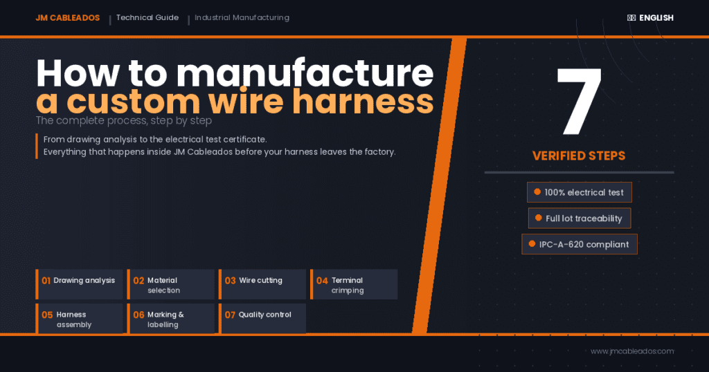
A custom wire harness is not simply “assembled”. It is designed, validated and manufactured following a structured process where every step serves a specific purpose. At JM Cableados, we have been manufacturing custom wire harnesses for industrial, automotive, electronics and medical sectors for years. This is the complete technical guide to how we do it.
If you have ever received a harness that did not fit your equipment, failed after a few hours, or was impossible to repair in the field — chances are one of these steps was not carried out correctly.
Step 1: Electrical Drawing Analysis and Customer Specifications
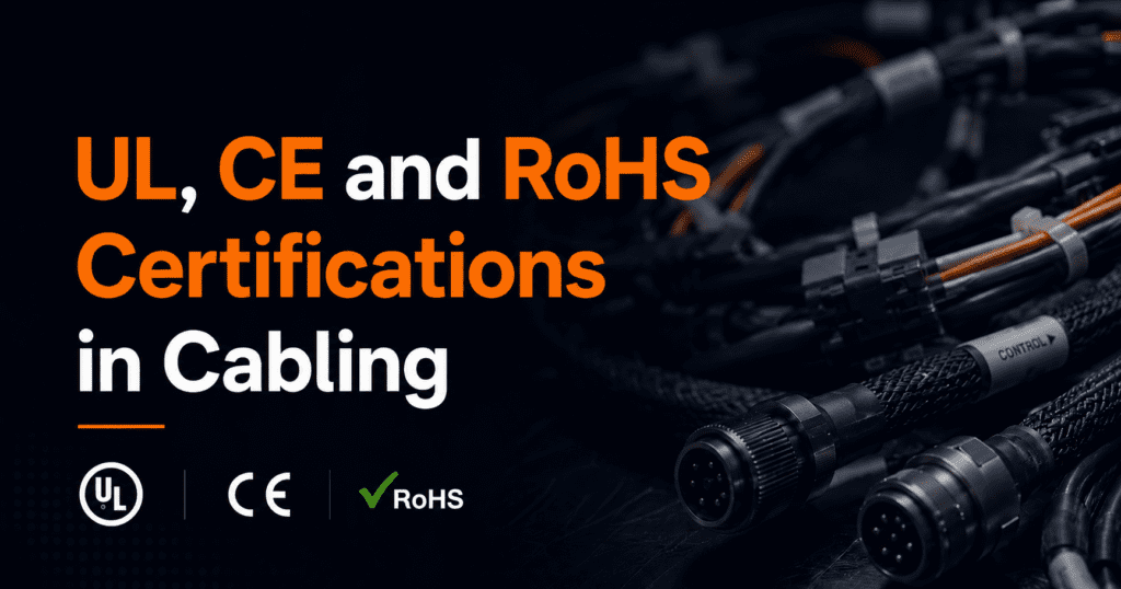
The process starts before touching a single cable. The technical team analyses the electrical drawing — or the signal list, if no drawing is available — and extracts the key parameters: number of conductors, cross-sections, lengths, connector type, flexibility requirements, operating temperature and applicable standards (UL, CE, RoHS, sector-specific).
This phase determines cost, lead time and project feasibility. A well-documented drawing reduces technical consultation rounds and speeds up delivery. If the customer does not have a drawing, JM Cableados offers a design service starting from a functional specification.
Step 2: Material Selection and BOM Definition
With the specifications validated, the harness Bill of Materials (BOM) is defined. This is the least visible phase for the customer, and the one that most determines the final result:
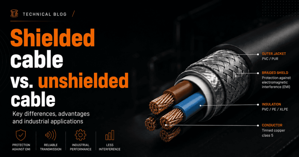
- Wire: cross-section in AWG or mm², insulation type (PVC, silicone, PTFE, LSNH), maximum temperature, applicable UL standard
- Terminals and connectors: family, pin pitch, contact material (brass, copper, silver), IP certification
- Protection: heat-shrink tubing, PET braiding, PA spiral wrap, corrugated conduit
- Labelling and marking: per customer standard or IPC standard
| Technical data: Wire insulation selection determines the full temperature range of the harness. PVC insulation limits the assembly to +105°C, while silicone insulation allows continuous operation up to +200°C. |
Step 3: Wire Cutting and Preparation
Conductors are cut to the lengths specified on the drawing. For medium and large production runs, cutting is performed with programmable automatic machines guaranteeing tolerances of ±1 mm and automatic stripping at both ends. For short runs or prototypes, cutting is manual using calibrated tools.
Insulation stripping is a critical operation: if excessive, the conductor is unnecessarily exposed; if insufficient, the crimp will be made on the insulation rather than on the conductor, resulting in increased contact resistance.
| Workshop insight: A 5 mm error in wire length can mean the harness does not close properly inside the equipment. Traceability for each cutting batch — length, operator, tool — is part of our process control at JM Cableados. |
Step 4: Terminal Crimping
Crimping is the most critical operation in the process. Each stripped conductor receives a mechanically crimped terminal, forming a gas-tight joint that guarantees maximum electrical conductivity and corrosion resistance.
Parameters controlled at every crimp are:
- Terminal pull-force test, with minimum value per IEC 60352-2
- Crimp height, measured with a calibrated micrometer
- Visual or metallographic cross-section inspection on lot samples
| Technical data: A correct crimp must exceed the minimum pull-out force defined by IEC 60352-2. For an AWG 22 conductor with a copper terminal, that minimum force is 30 N. Below that value, the connection is rejected. |
Step 5: Custom Wire Harness Assembly on Mounting Jig
With conductors cut and crimped, assembly begins on a mounting board or jig. This phase integrates all harness elements:
- Insertion of terminals into connector housings, with locking verification by pull-force check
- Grouping and routing of conductors according to the electrical drawing layout
- Application of protection: heat-shrink tubing, PET braiding, PA spiral wrap, corrugated conduit
- Fitting of cable ties, cable glands and mechanical accessories
The assembly sequence on the jig is not random: it follows the drawing sequence to avoid conductor crossovers that increase harness length and weight.
Step 6: Marking and Labelling
The finished harness is identified with labels showing the customer reference, lot number, manufacturing date and, when required, component traceability. Labels are selected based on the end-use environment: resistance to oils, extreme temperatures, solvents or UV radiation.
| Engineering note: For aggressive industrial environments we use permanent-adhesive labels on polyester or polyimide (Kapton), with resin printing resistant to +150°C and continuous hydrocarbon exposure. |
Step 7: Quality Control and Electrical Testing (100% Individual)
Before shipment, every harness goes through a complete verification protocol:
- Electrical continuity of all conductors (100% individual test)
- Absence of short circuits between signals
- Insulation resistance, when the application requires it
- Visual inspection per IPC-A-620 Class 2 or Class 3 depending on sector
- Terminal pull-force test by lot sampling
| Workshop insight: At JM Cableados, 100% of harnesses leave the factory with their own electrical test certificate. We do not apply statistical sampling for continuity testing: every single unit is individually verified. |
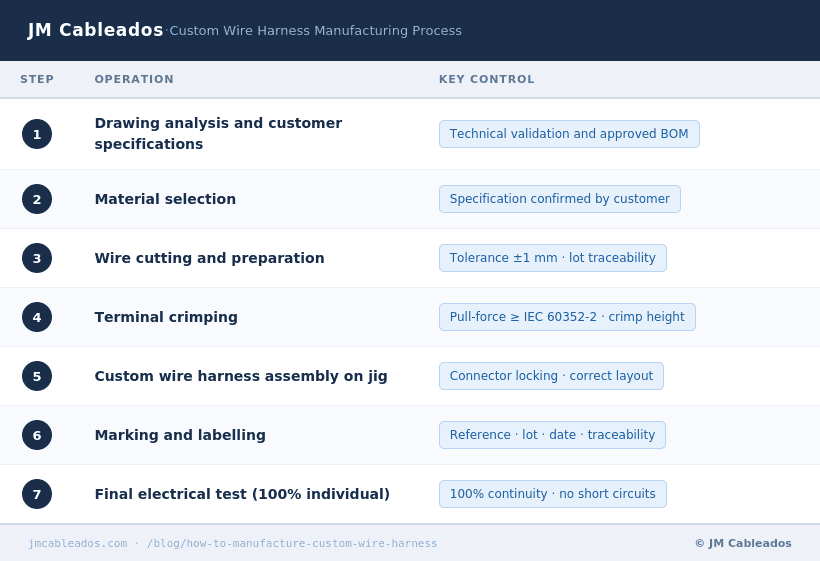
Custom Wire Harness Manufacturing Process Summary
| Need a custom wire harness or cable assembly? At JM Cableados we manufacture custom wire harnesses with fast lead times, no unreasonable minimum order quantities, and a test certificate for every unit. Tell us about your project. Contact us: info@jmcableados.com |