When should you use each one?
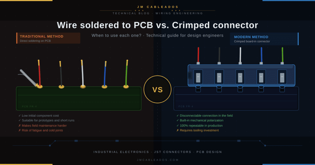
In the design of a custom harness or cable assembly, one of the most common —and most underrated— decisions is how to terminate the ends that connect to the board. Direct soldering or using a crimped connector are two entirely different worlds in terms of productivity, reliability, and long-term cost.
What are we actually talking about?
When we talk about tinned wire on PCB, we mean the traditional technique of soldering the conductor end directly onto the PCB pad. It is the oldest solution, found in prototypes, repairs, and low-volume products since the 1960s.
On the other side are crimped board-in connectors: the conductor is terminated with a crimped terminal, which is inserted into a plastic housing that mechanically anchors to the board. Manufacturers like JST have developed complete series for this: SDN, SCN, SJN, SZN, SAN, and the individual SIN terminals, among others.
| Design note: At JM Cableados we regularly work with JST reduced-pitch connectors (1.5 mm to 3.96 mm) for wiring in sectors such as industrial electronics, automotive, and medical equipment, where mounting density and connection reliability are critical. |
The direct comparison
| TRADITIONAL METHOD Direct soldering on PCB | MODERN METHOD Crimped board-in connector |
| ✓ Minimal upfront cost (no additional components) ✓ Suitable for prototypes and very short runs ✓ No pitch or form factor constraints ✗ Permanent connection: hinders maintenance ✗ Solder wicks into wire → reduces flexibility and fatigue life ✗ Longer assembly time in production ✗ Risk of solder bridges and cold joints ✗ No module interchangeability | ✓ Disconnectable: easy maintenance and replacement ✓ Crimping ensures a flexible transition zone ✓ Built-in polarisation: prevents polarity reversal ✓ Full repeatability in mass production ✓ RoHS/UL compliant without lead solder ✗ Requires investment in crimping tooling ✗ Connector pitch constrains PCB layout ✗ Additional terminal and housing stock required |
The SIN terminal: the middle ground
There is an intermediate solution that many procurement engineers are unaware of: the JST SIN terminal. This terminal is crimped to the wire, inserted into a PCB hole, and then soldered. The key difference from direct tinning is that the solder does not wick into the conductor, as the crimp zone acts as a physical barrier.
The result is a permanent connection —ideal for jumper wires and external circuits— with better solderability than traditional tinning and without sacrificing cable flexibility in the working zone. Available for wire gauges from AWG #30 to AWG #10, covering virtually the entire industrial wiring spectrum.
| Technical note: The SIN-01T-1.8N terminal features a special reduced-tip design that lowers the insertion force into the PCB, improving ergonomics in high-volume assemblies. |
Most common JST board-in families in industrial wiring
| SDN 3.96 mm pitch · Power/signal | |
| Current rating | 7 A (AWG18) |
| Voltage | 250 V AC/DC |
| Temp. | −25 / +85 °C |
| Wire | AWG 22–18 |
| Circuits | 2–12 |
| SCN 2.5 mm pitch · High density | |
| Current rating | 3 A (AWG22) |
| Voltage | 250 V AC/DC |
| Temp. | −25 / +85 °C |
| Wire | AWG 28–22 |
| Circuits | 2–16 |
| SAN 2.0 mm pitch · Compact | |
| Current rating | 2 A (AWG24) |
| Voltage | 250 V AC/DC |
| Temp. | −25 / +85 °C |
| Wire | AWG 30–24 |
| Circuits | 2–15 |
| SJN 2.0 mm pitch · Side-entry | |
| Current rating | 3 A (AWG22) |
| Voltage | 250 V AC/DC |
| Mount. height | 2,8 mm |
| Wire | AWG 28–22 |
| Circuits | 2–11 |
| SZN 1.5 mm pitch · Miniature | |
| Current rating | 0,7 A (AWG26) |
| Voltage | 50 V AC/DC |
| Mount. height | 4,25 mm |
| Wire | AWG 30–26 |
| Circuits | 2–13 |
| SIN Single terminal · Direct PCB | |
| Current rating | Wire |
| Temp. | −25 / +85 °C |
| Wire | AWG 30–10 |
| Type | Crimp + solder |
| Standards | UL / CSA |
When should you choose each solution?
There is no single answer. The choice depends on production volume, field maintenance requirements, and electrical specifications. This table summarises the most common criteria:
| Scenario | Direct soldering | SIN Terminal | board-in connector |
| Prototype / 1 unit | Optimal | Valid | Overkill |
| Short run (10–500 units) | Acceptable | Recommended | Recomendado |
| Long run (>500 units) | Not recommended | Possible | Óptimo |
| Field-maintainable equipment | Avoid | Avoid | Óptimo |
| Permanent sealed connection | Valid | Óptimo | With seal |
| High vibration environment | Fatigue risk | Acceptable | With lances |
| High current (>5 A) | Bridge risk | Depends on AWG | SDN (7A) |
The hidden cost: the real price of soldering in production
Many purchasing departments choose direct soldering because the unit cost appears lower: no terminal, no housing. This is a classic partial cost analysis trap.
| 3× longer cycle time with manual soldering vs. crimping | ~8% typical defect rate in manual soldering (IPC-A-620 class 2) | 0 chance of replacing a field module without rework |
Automatic crimping with an applicator guarantees a consistent crimp geometry, verifiable by cross-section inspection, and 100% repeatable regardless of the operator. This translates directly into fewer rejects, less rework, and zero claims for conductor fatigue.
| From the shop floor: At JM Cableados, when a customer comes to us with a design specifying direct soldering for runs over 200 units, we always analyse together whether a board-in connector can offset the additional component cost with savings in assembly and field warranty claims. In most cases, the answer is yes. |
Polarisation and assembly error considerations
One of the strongest arguments in favour of the crimped connector is built-in mechanical polarisation. The SDN, SCN and SAN series include a polarising boss —an asymmetric protrusion on the housing— that makes it physically impossible to reverse the connection.
A directly soldered wire, on the other hand, has no protection against polarity reversal or connection to the wrong pad, an error that can destroy SMD components in microseconds. For medical or functional safety equipment, this is not a minor detail: it is a design requirement.
Conclusion: choose based on your product’s life cycle
The choice between soldering and crimped connectors is not a matter of technical preference: it is a life cycle engineering decision. Direct soldering is fast and cheap for a prototype; the board-in connector is the professional solution for any product that will be manufactured in series, maintained in the field, or subjected to vibration and thermal cycling.
SIN terminals occupy that intermediate space: permanent connection with the mechanical reliability of crimping. Knowing when to use each one makes the difference between a wiring assembly that lasts and one that generates claims.